Introduction
Use this guide to assemble the carrier plate for the PS-s module.
Important! Wear gloves while handling the plate: The carrier plate is coated with ESD-safe material. To prevent degradation of the coating by finger grease and dirt, avoid direct contact with the plate.
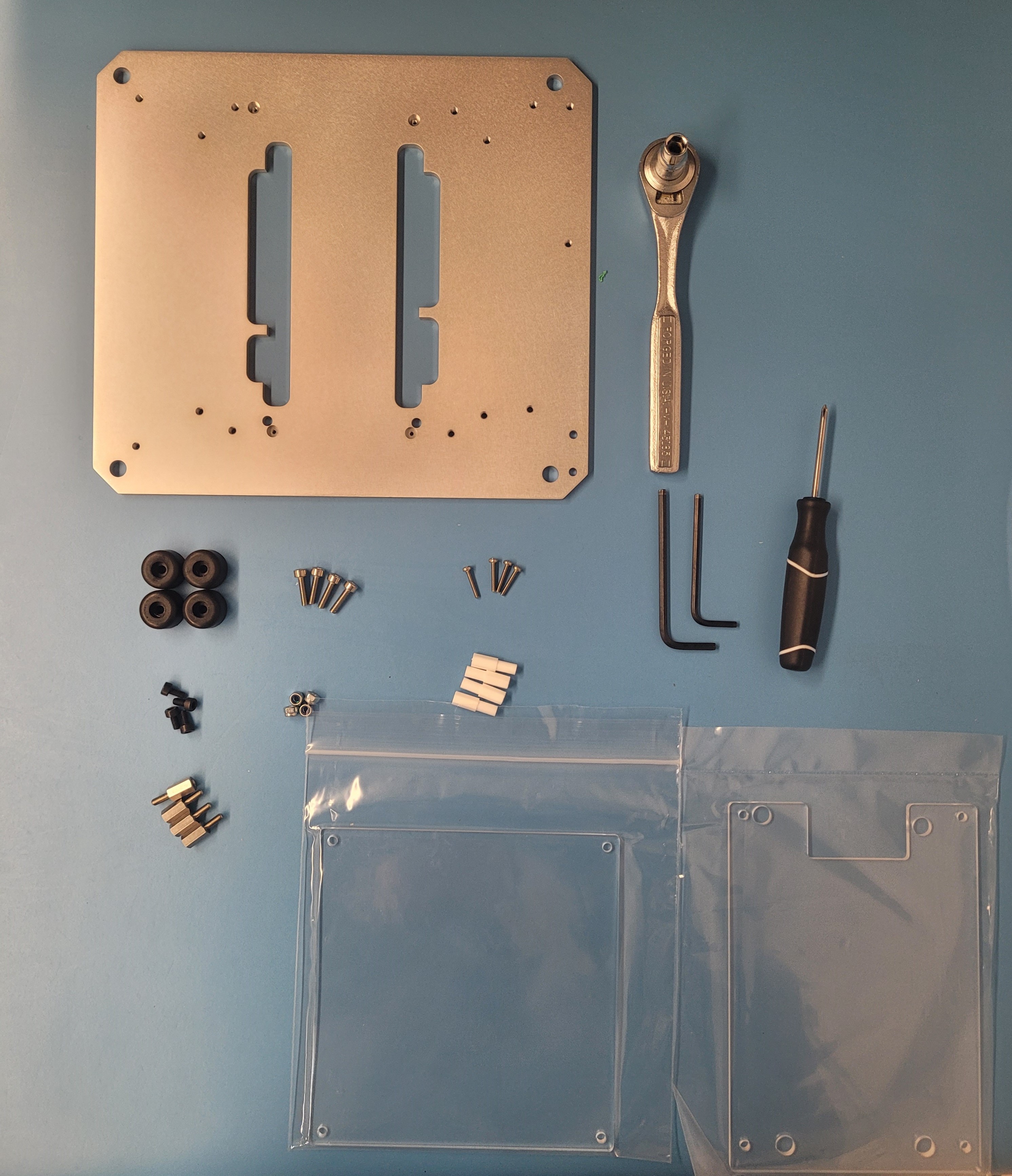
Materials
| Part | Quantity |
|---|---|
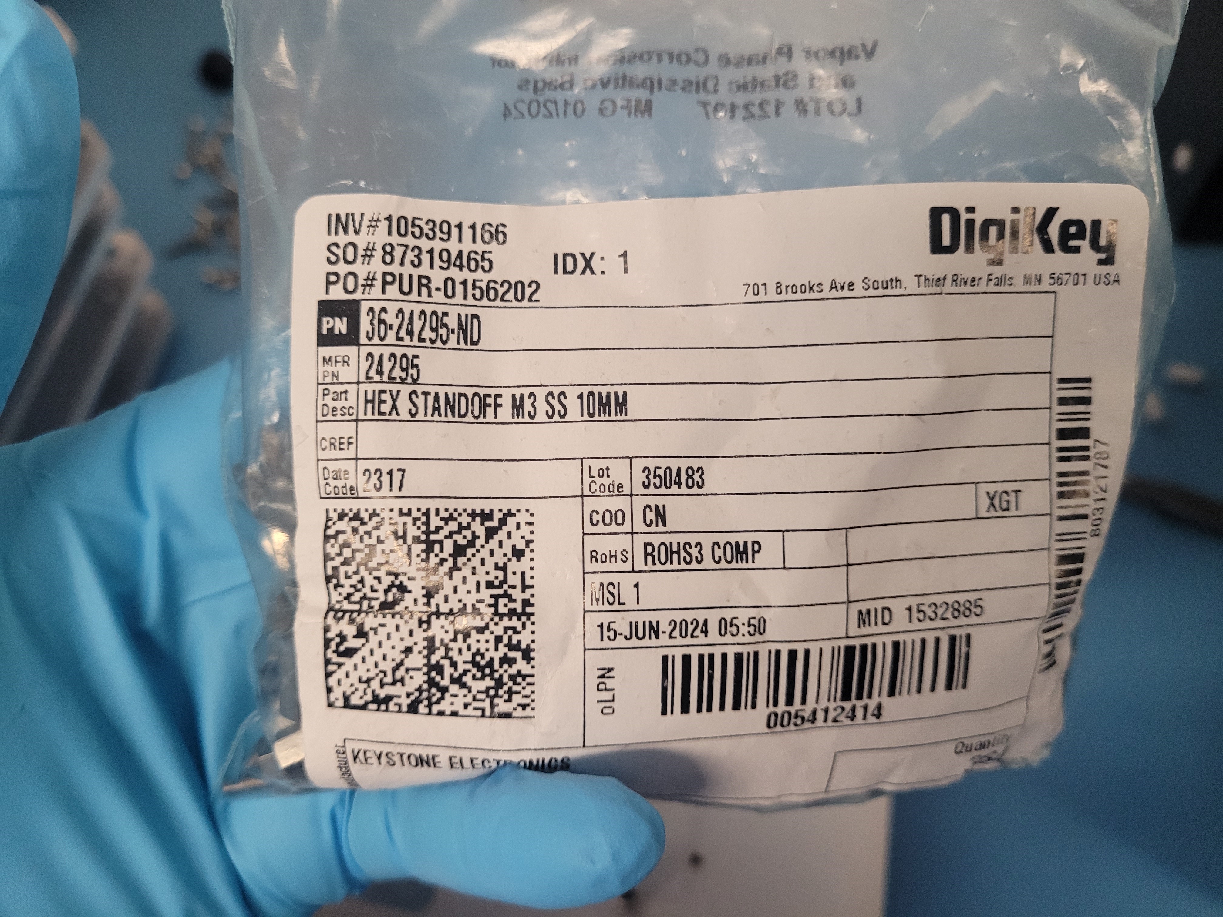
| Hex Standoff M3 SS 10mm | 4 |
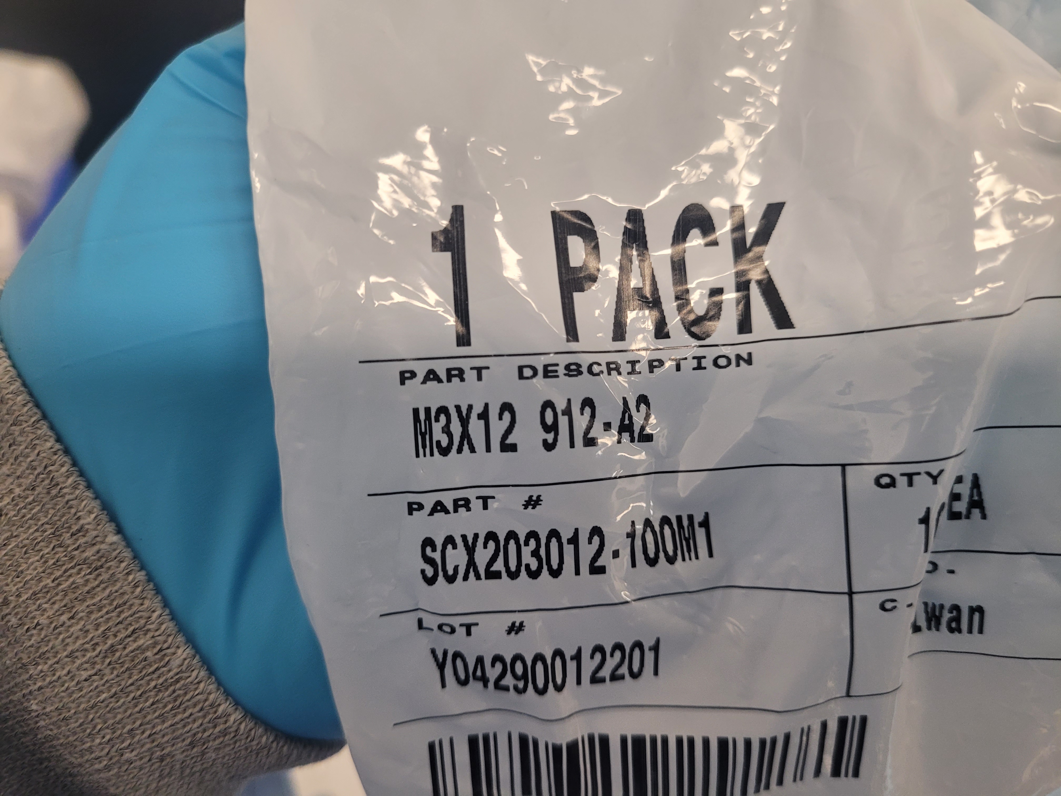
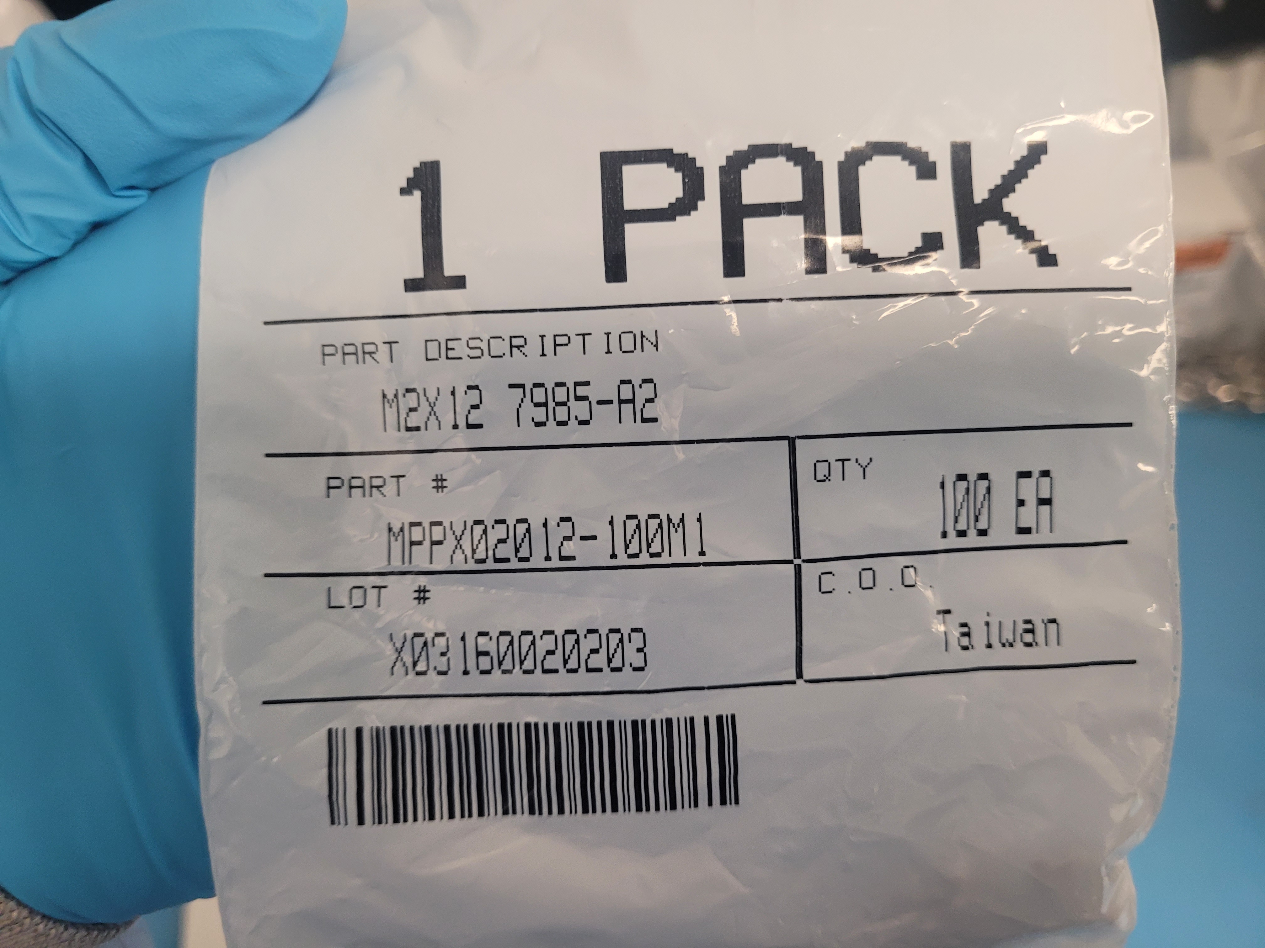
| M2x12 | 4 |
| M3x12 | 8 |
| M3x6 | 4 |
| Nylon in thin nut 3x.5 | 4 |
| 3D printed Hex Standoff M2x10mm | 4 |
| Black rubber feet | 4 |
| Bottom acrylic | 1 |
| Top acrylic | 1 |
| Plate | 1 |
| Ratchet | 1 |
| Screw driver | 1 |
| Allen wrench | 2 |
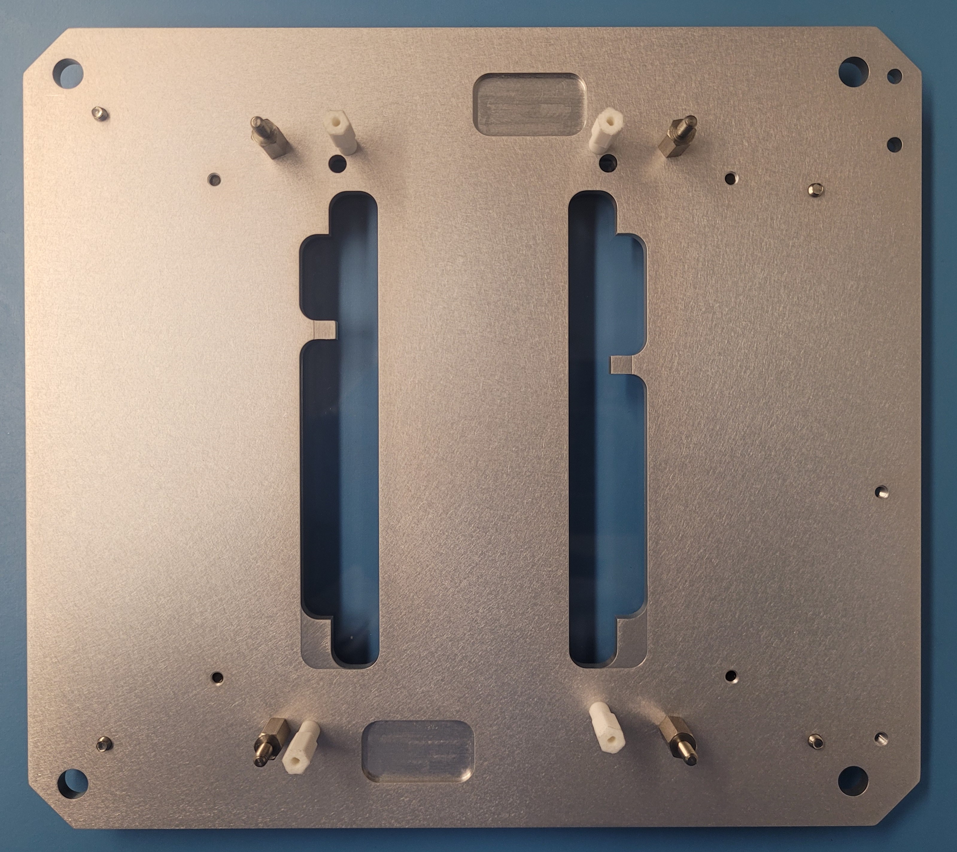
Orientation of the plate
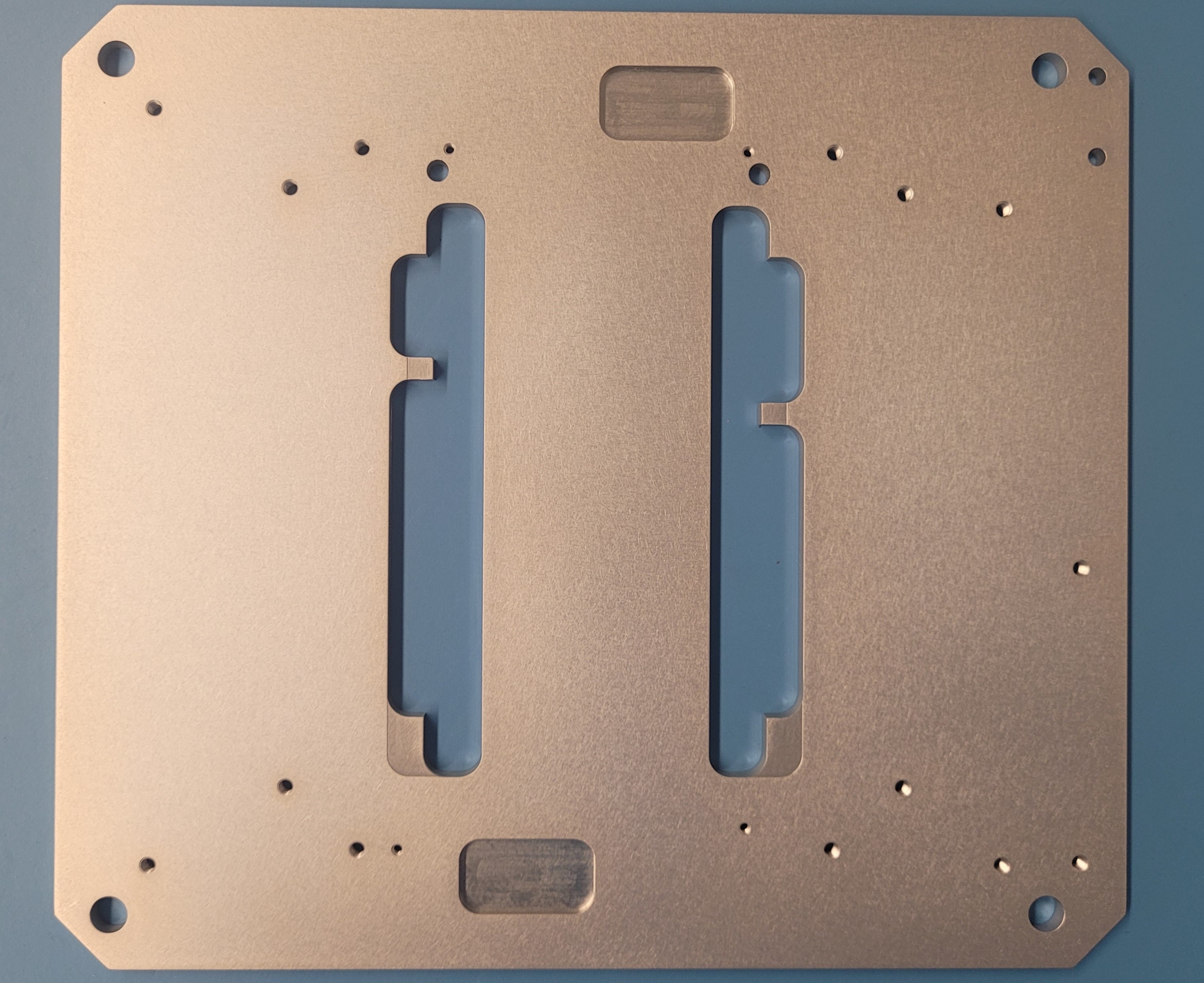 Top side
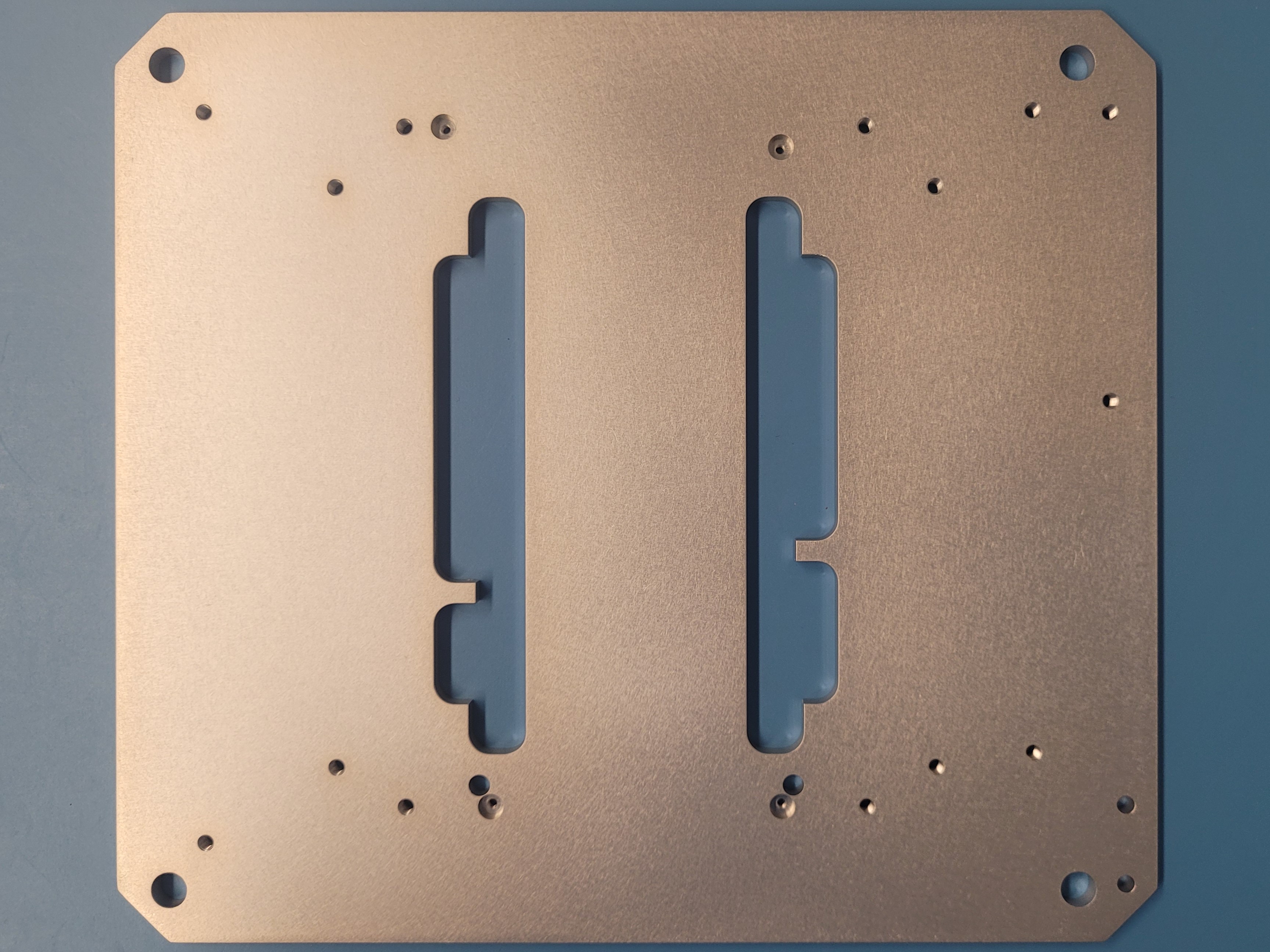 Bottom side
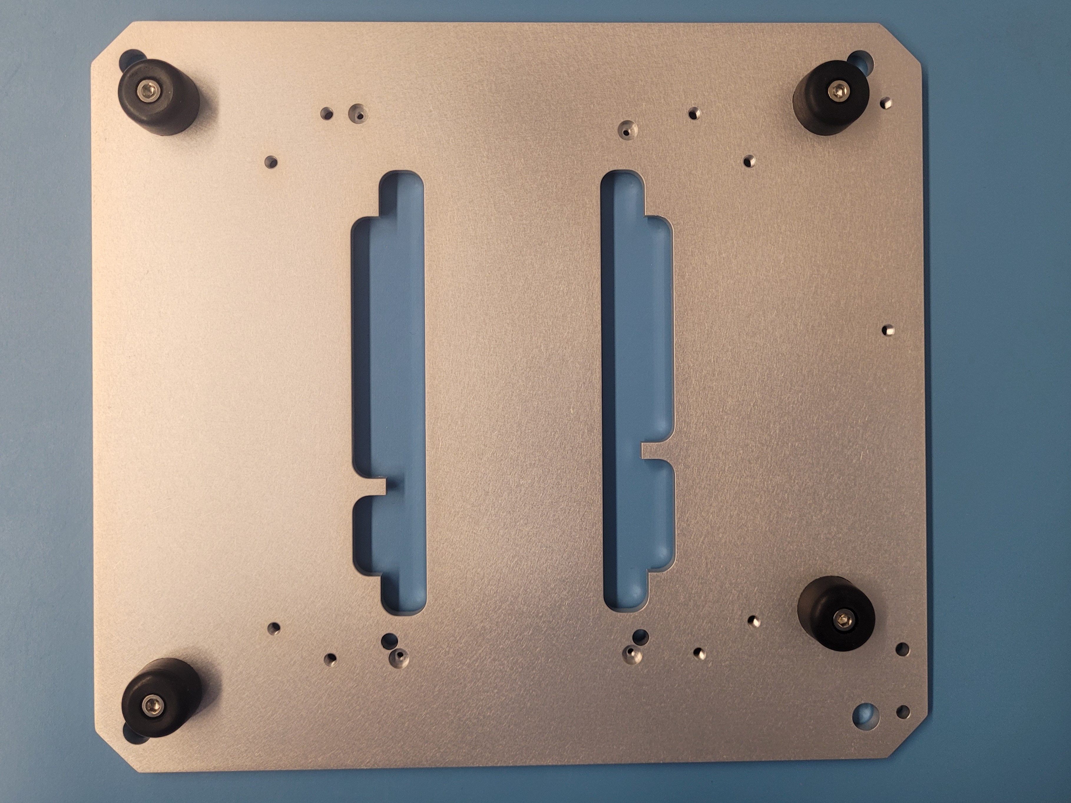
Step 1: Feet
Preparing the feet
Materials
| Part | Quantity |
|---|---|
| Black rubber feet | 4 |
| M3x12 | 4 |
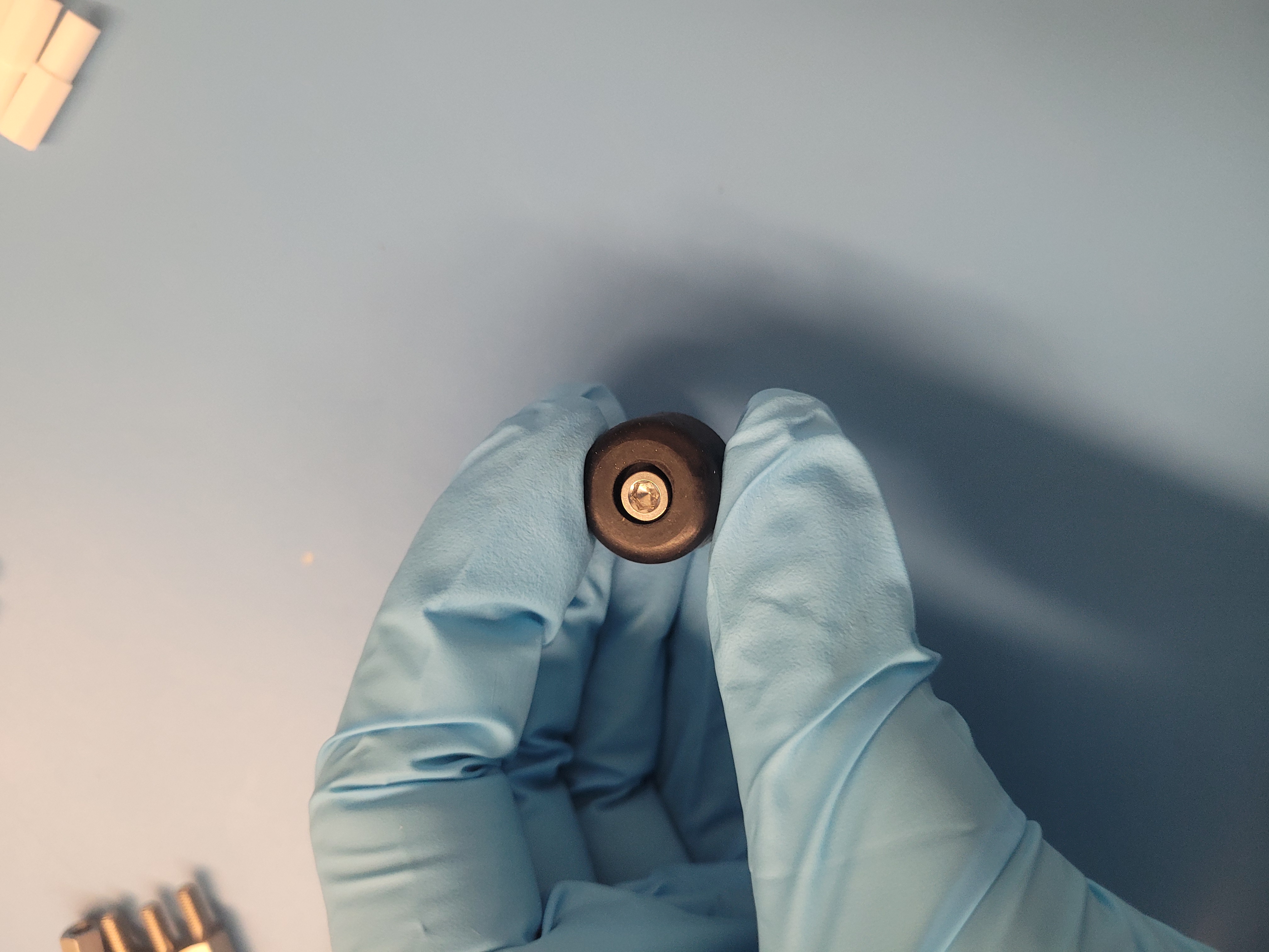
- Insert the M3x12 screws into the feet
Securing the feet in place
- Insert the feet into the designated holes on the underside of the plate and secure them with screws.
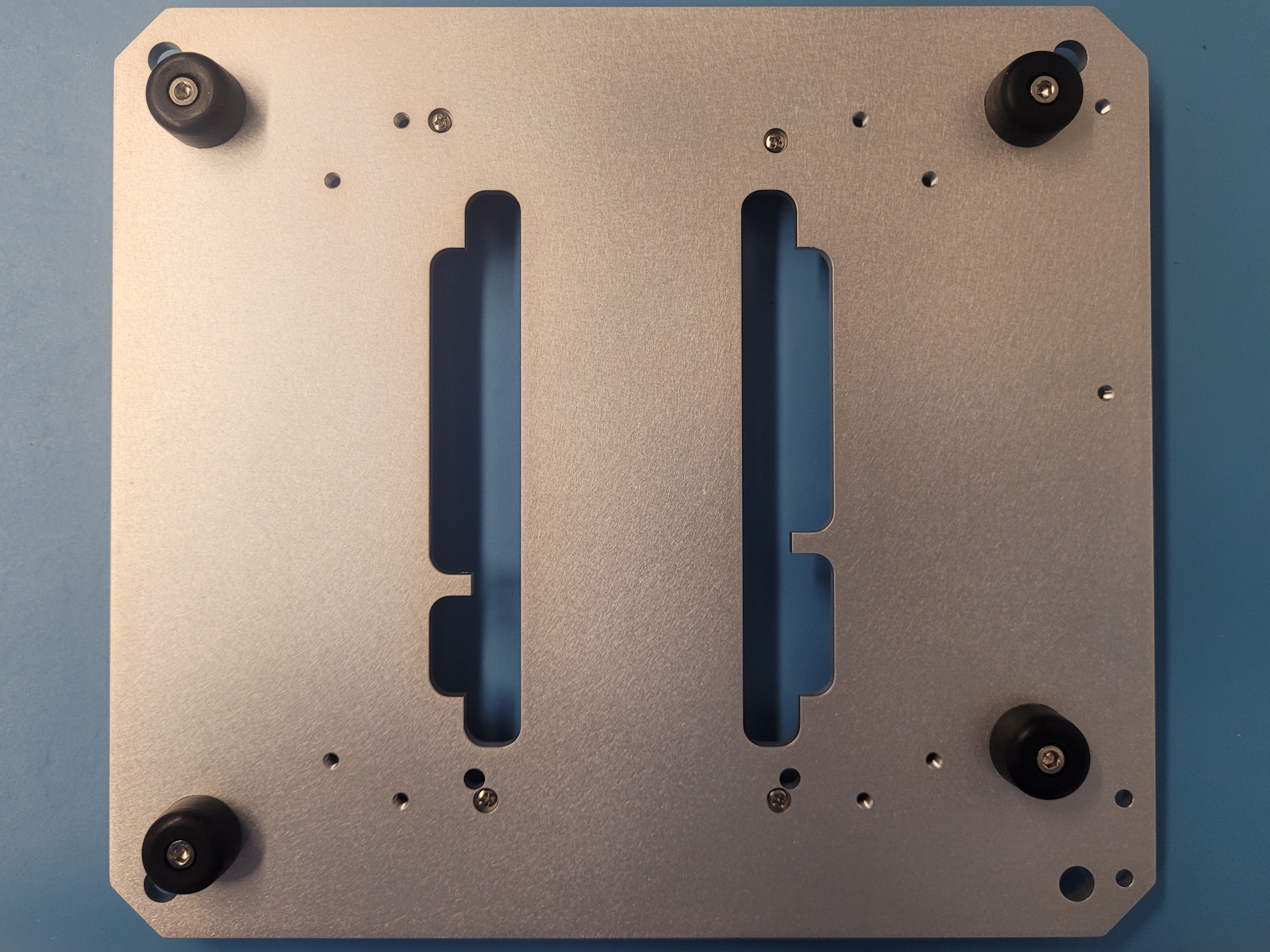
It should look like this:
Step 2: M2 screws
Materials
| Part | Quantity |
|---|---|
| M2x12 | 4 |
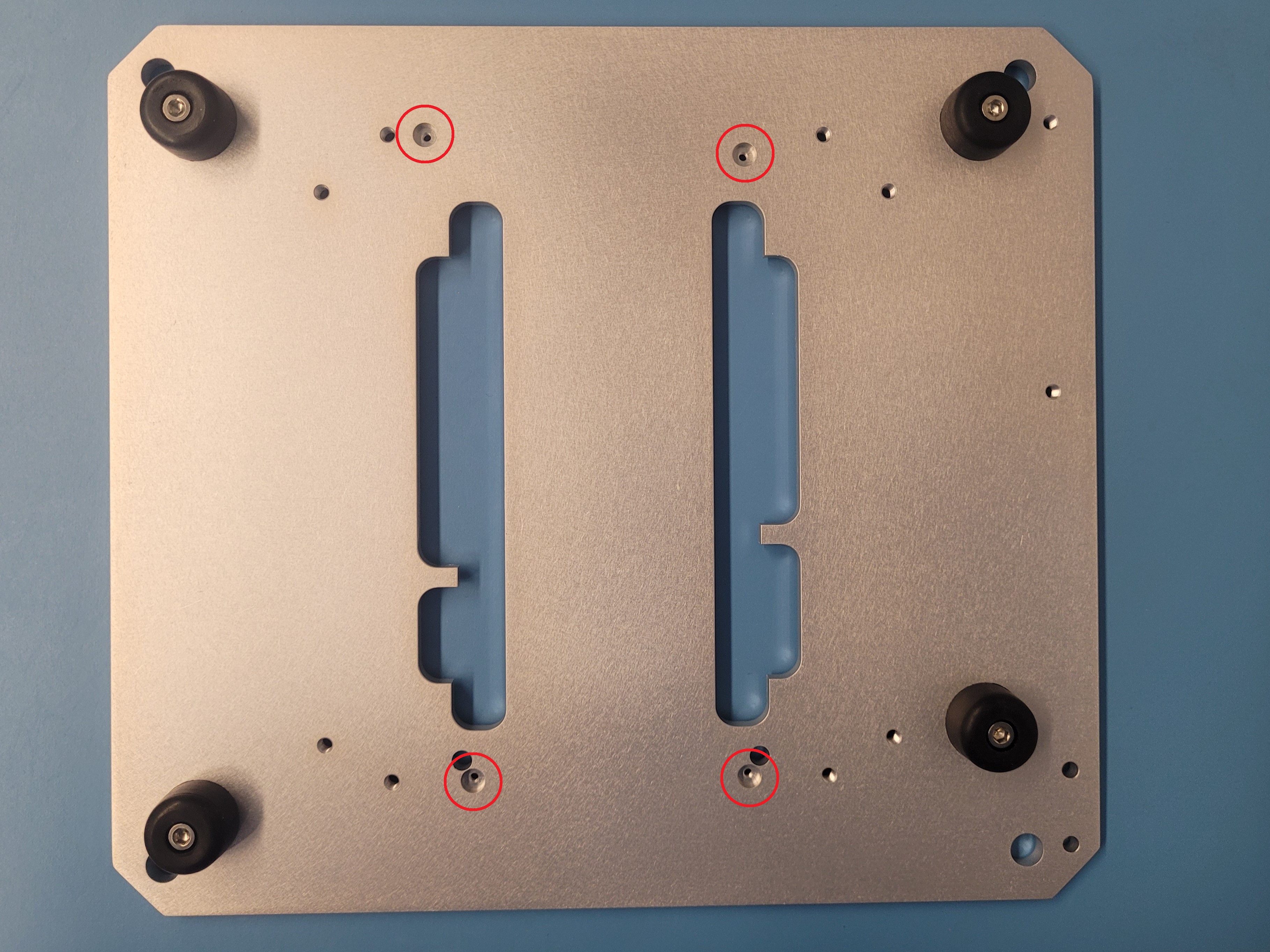
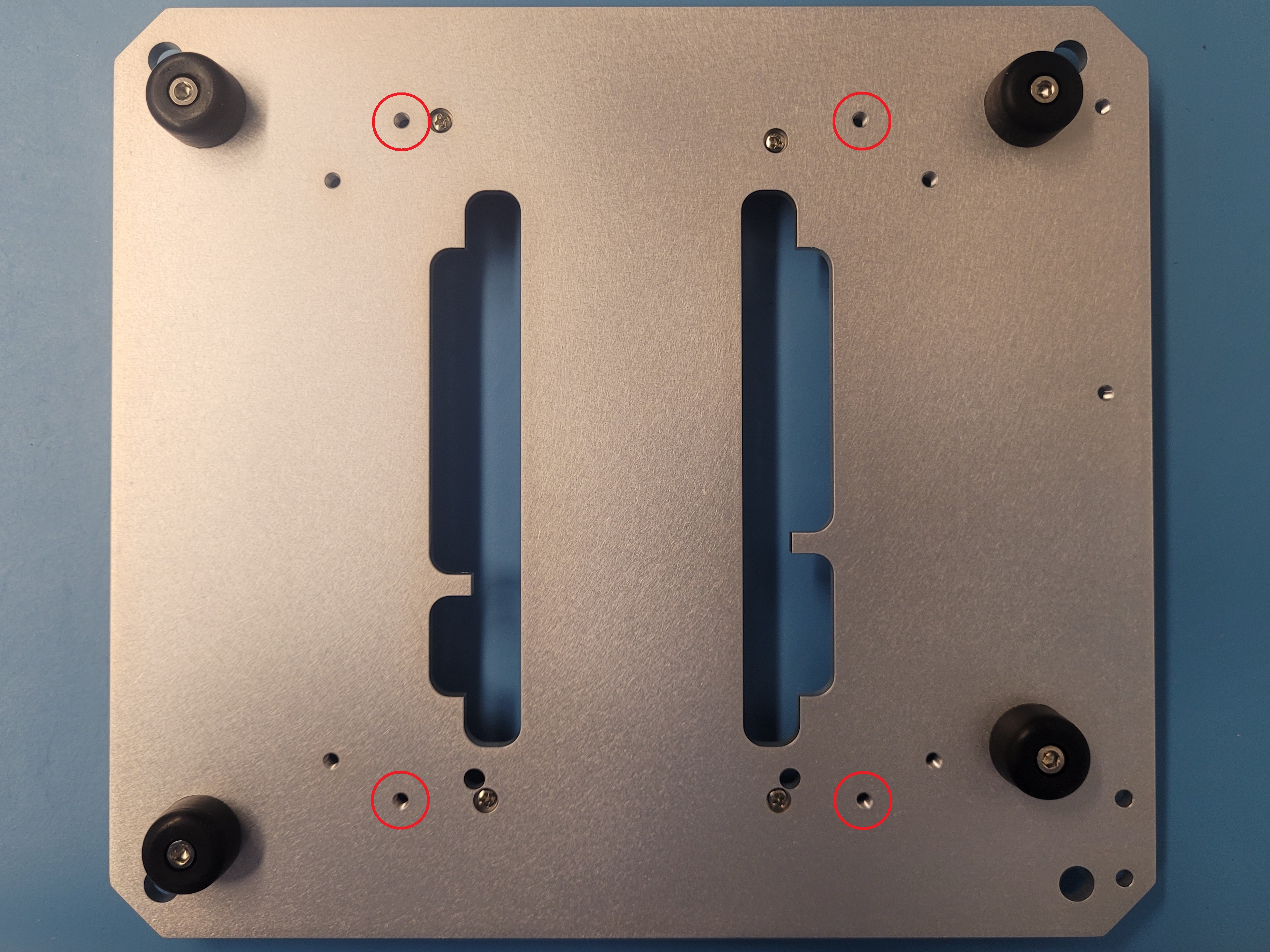
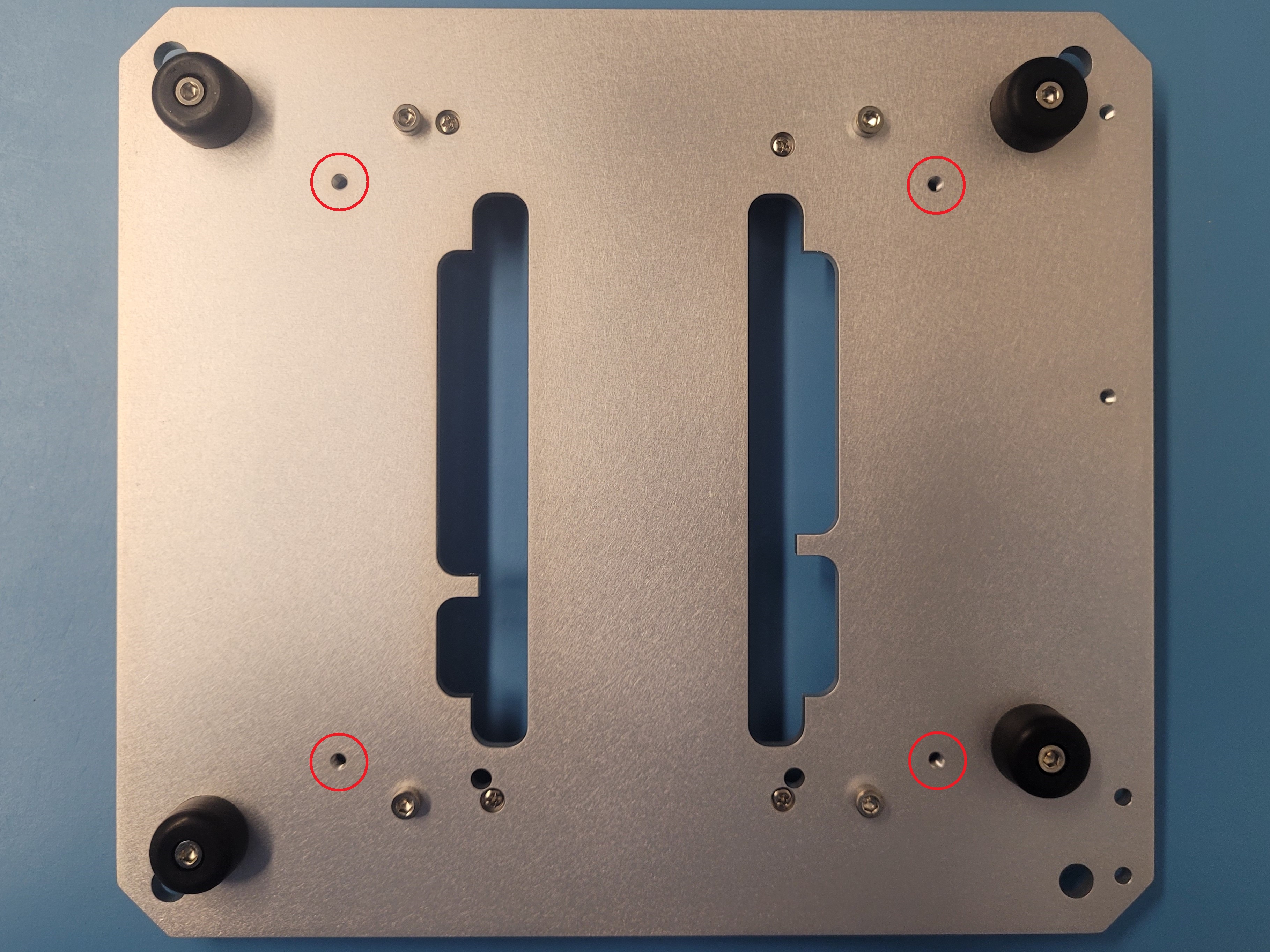
- After securing the feet in the plate, locate the socketed holes
- Use a screwdriver to tighten the M2x12 screws.
- This screws will hold down the 3D printed standoff (See Step 6 for installation)
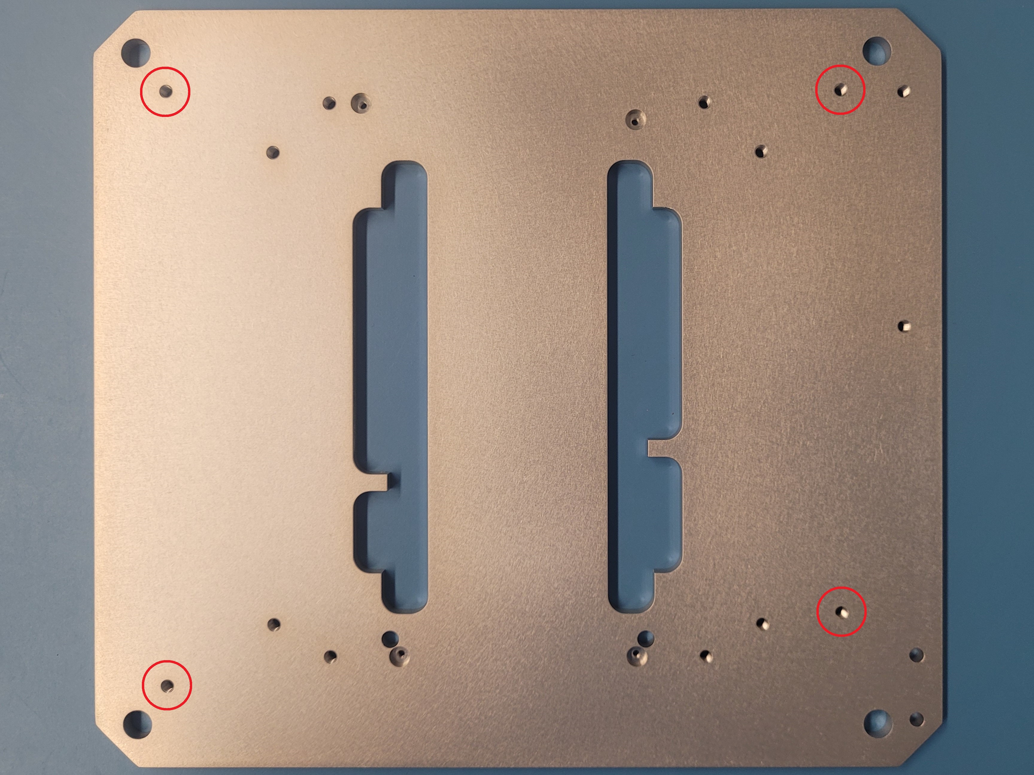
Step 3: M3 screws
Materials
| Part | Quantity |
|---|---|
| M3x12 | 4 |
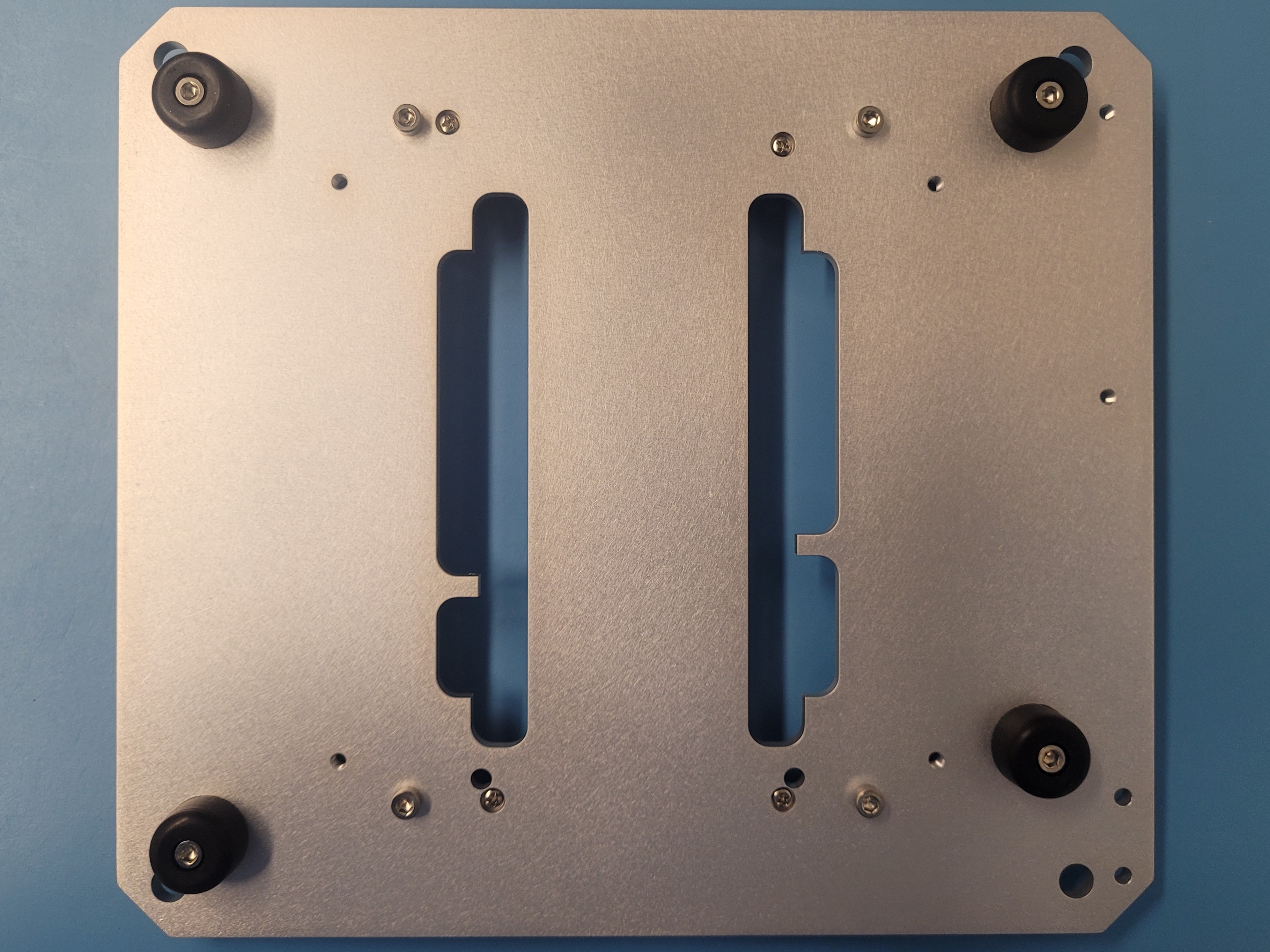
- Locate the holes near the socketed holes with the M2 screws
- Use the allen key to tighten the M3x12 screws.
- These hold down the metal hex standoffs
Step 4: Acrylic bottom
Materials
| Part | Quantity |
|---|---|
| M3x6 | 4 |
| Bottom Acrylic | 1 |
- Locate the last 4 screw holes in the plate
- Take the acrylic plate and align it with the screw holes
- The acrylic plate fits in only one position
- Place and use the allen key to tighten the M3x6 screws (black).
- The screws tighten with a little bit of a play, and has a small clearance with the holes of the acrylic plate
After installing it, it should look like this:
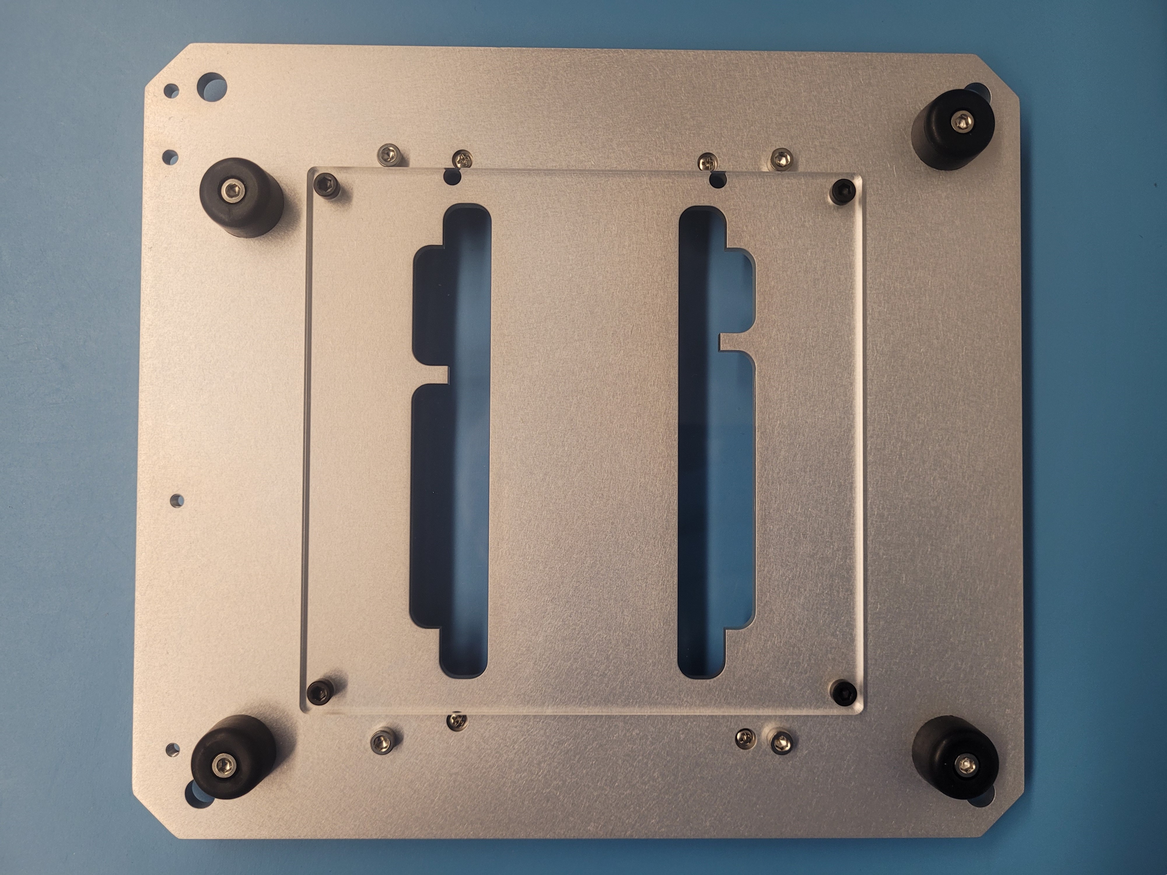
Bottom section is completed
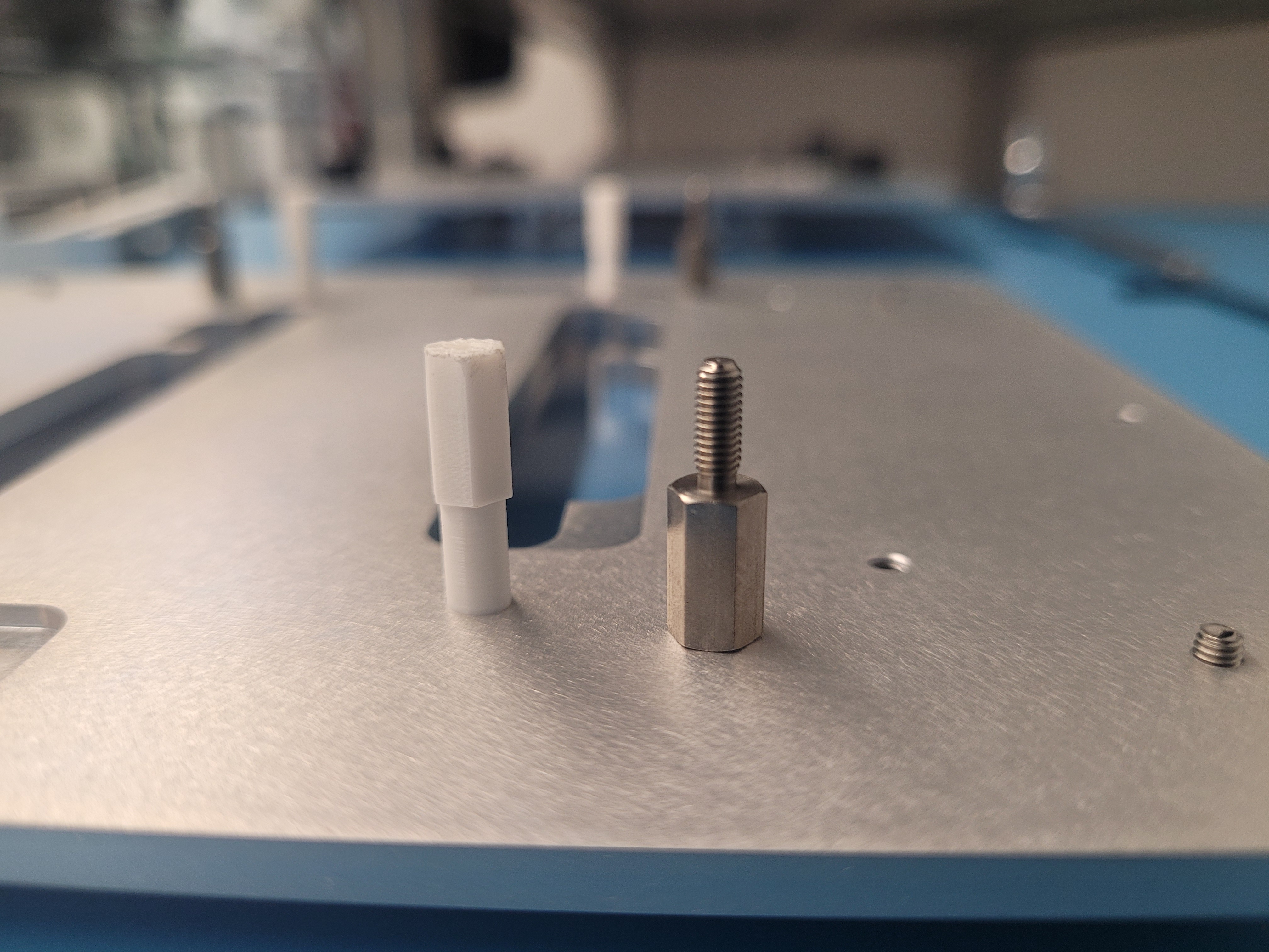
Step 5: Metal Standoffs
Turn around the carrier plate
Materials
| Part | Quantity |
|---|---|
| Hex Standoff M3 SS 10mm | 4 |

- Locate the M3 screws that are sticking out
- Tighten the metal hex standoffs until secure
- These are the screws that hold down the top side acrylic plate with the nuts

Step 6: 3D printed standoffs
Materials
| Part | Quantity |
|---|---|
| 3D printed Hex Standoff M2x10mm | 4 |
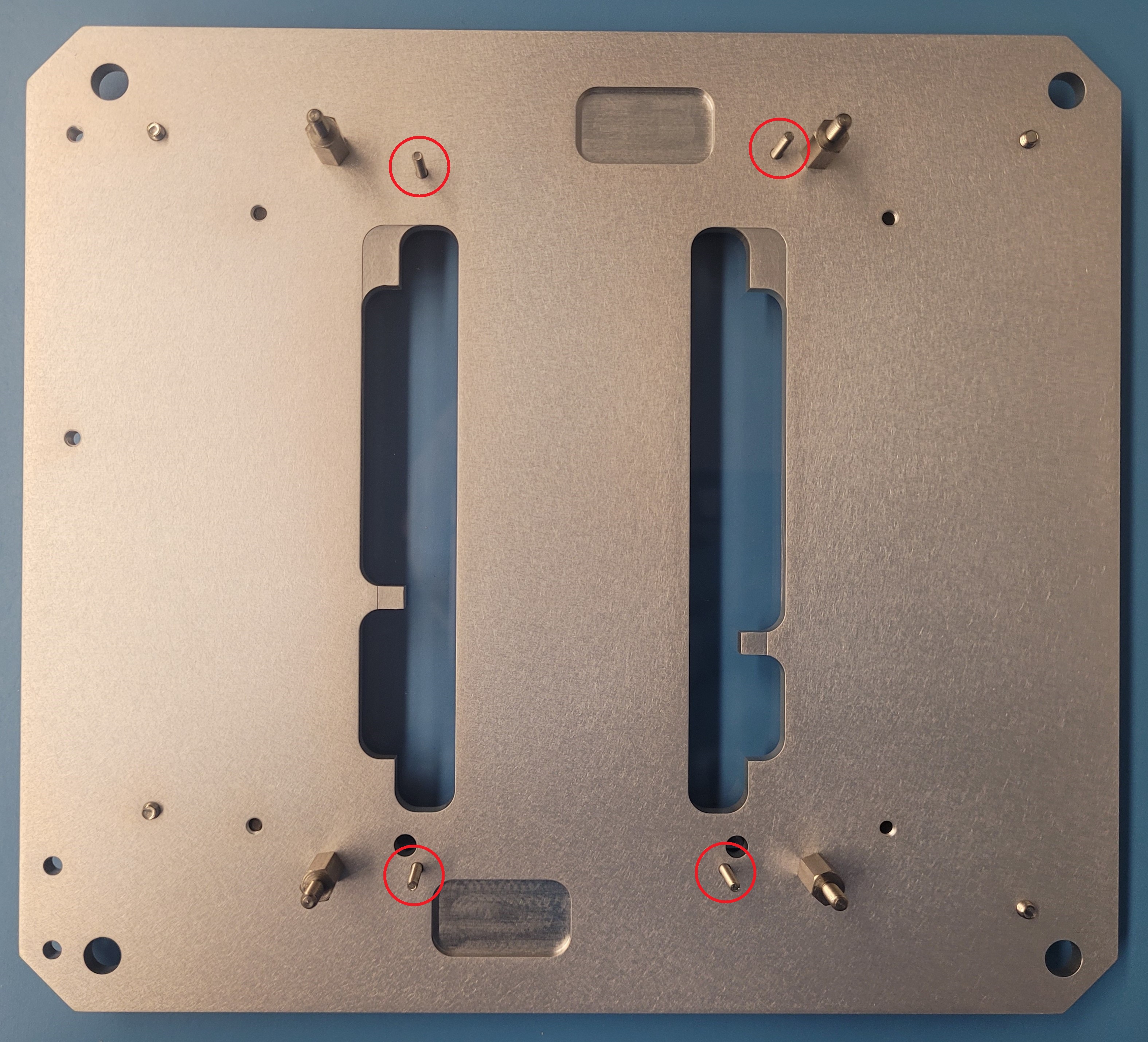
- Locate the M2 screws that are sticking out
- Tighten the 3D printed hex standoffs until secure
- It needs a slight pressure to install it and form the thread inside the barrel
Step 7: Acrylic top
| Part | Quantity |
|---|---|
| Acrylic Top | 1 |
| Nylon in thin nut 3x.5 | 4 |
- Align the outer holes from the acrylic top with the metal hex standoffs
- The acrylic top will only fit in one direction
- The inner holes should align with the 3D printed hex standoffs
- Using the wrench, tighten up the acrylic top using the nuts
- Do not over-tighten the nuts
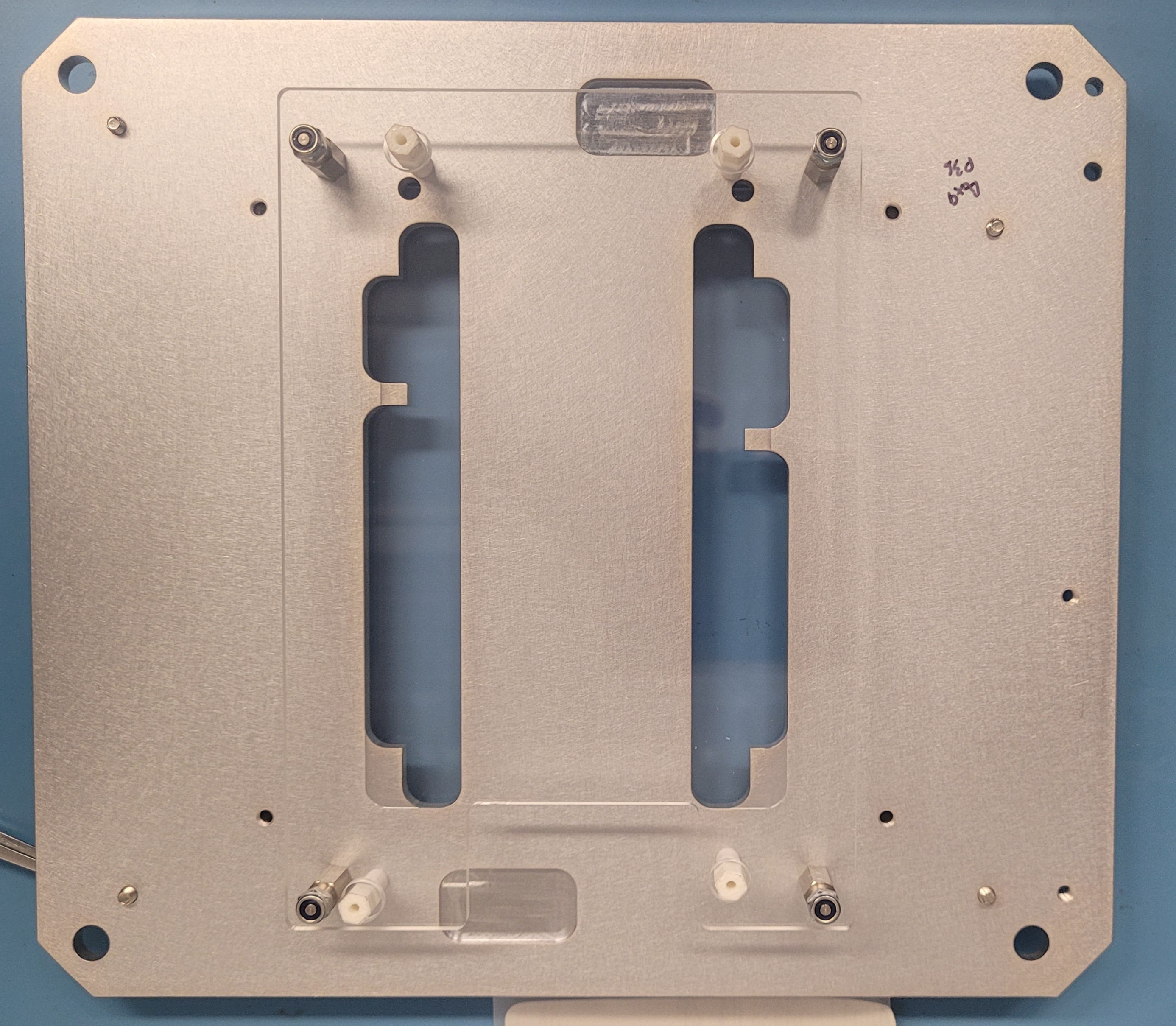
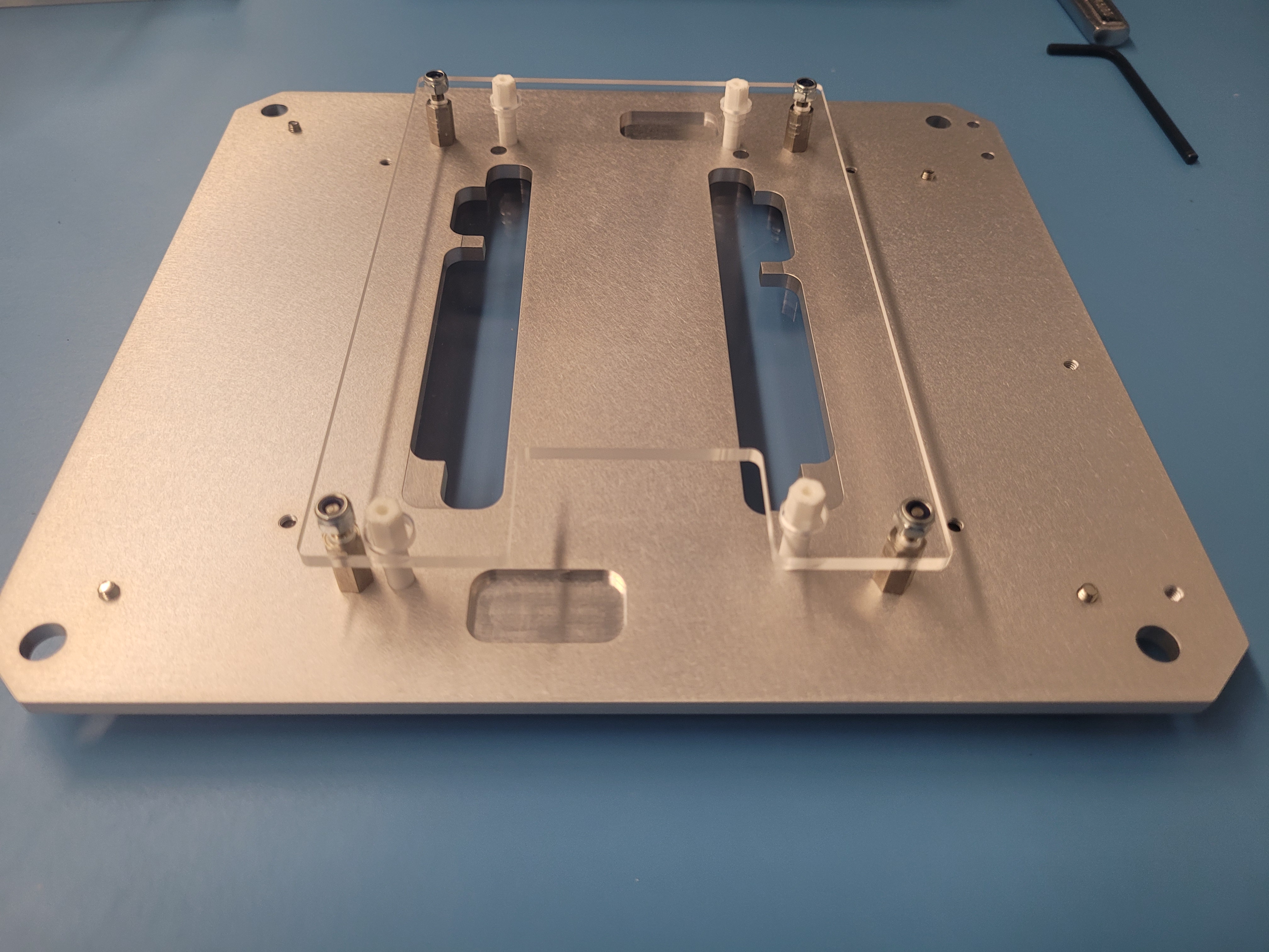
After this, you succesfully assembled the carrier plate for the PS-s Module.
PREVIOUSModule Carrier Box